- The Silent Killer of Remote Venues Mechanical Relay Bouncing and Phantom Coin Triggering
- Industrial Architecture Dual-Core STM32F407 vs ESP32-S3 Microcontroller Teleoperation Boards
- Optical Isolation Circuitry PC817 and 6N137 High-Speed Optocouplers for Complete Galvanic Separation
- Precision Pulse Generation Sub-Millisecond Hardware Timers for Bill Acceptor and Coin Mech Emulation
- Telemetry and Bi-Directional Feedback Optical Ticket Sensor Verification and Hopper Out-of-Stock Telemetry
- FAQ Section
When you manage a remote live arcade venue spanning hundreds of machines, your entire business model hinges on the reliability of the bridge between the digital payment gateway and the physical machine hardware. I have spent the last 12 years working directly with arcade PCB schematics, power distribution layouts, and digital signal processing logic. What I have seen repeatedly in the market is operators losing thousands of dollars monthly simply because they opted for consumer-grade smart relays instead of purpose-built industrial control boards.
In our Panyu manufacturing base, our 50-person R&D team has meticulously analyzed the failure points of hybrid arcade setups. It all boils down to how cleanly and accurately a digital command originating from a mobile app halfway across the world is translated into a physical electrical pulse on a JAMMA harness. This article will dissect the engineering behind true industrial IoT controller boards for arcade teleoperation, the physics of pulse conversion, and the rigorous QA standards we mandate before any hardware leaves our 15,000-square-meter facility. For factory-direct procurement and comprehensive engineering specs, consult our master guide on cloud arcade machine teleoperation and turnkey engineering.
> Test Our Hardware Live > Before we dive deep into the circuitry, we invite all technical directors and operators to experience our teleoperation latency firsthand. Request a Live WebRTC test sandbox link or our APK demo credentials by contacting our engineering team. You can control a physical claw machine or coin pusher in our Panyu lab with under 80ms latency from your own device, monitoring the hardware pulse conversion in real-time.
The Silent Killer of Remote Venues Mechanical Relay Bouncing and Phantom Coin Triggering
> Industrial IoT arcade controller boards use high-speed PC817 and 6N137 optocouplers to achieve complete galvanic separation between sensitive 3.3V/5V microcontroller logic and noisy 12V/24V coin mechs and motors. Powered by dual-core STM32F407 processors, the board emulates deterministic 50ms active-low coin pulses with sub-millisecond precision, completely eliminating false credit triggers.
One of the most persistent and revenue-draining issues in remote arcade operations is the phenomenon of phantom coin triggering. Venue owners often approach us complaining that their accounting backends show 1,000 credits purchased by players, but the physical game board’s internal audit registers 1,050 credits. Where do these extra credits come from? The answer lies in the physics of cheap mechanical relays and electrical noise.
Many entry-level remote payment solutions use basic mechanical relay modules to short the coin line to the ground pin. When a mechanical relay closes its contacts, the metal plates do not simply touch and stop. Microscopically, they bounce against each other several times over the span of a few milliseconds before settling. If the game board’s microcontroller is scanning the coin input pin with a fast polling rate or using edge-triggered interrupts without proper hardware debouncing, it will interpret those microscopic bounces as multiple rapidly inserted coins. This is known as contact bounce or relay chatter.
Over a month, across a venue of 200 machines, this bouncing effect can result in thousands of phantom credits. Players receive extra game time they did not pay for, effectively destroying the mathematical RTP (Return to Player) model you carefully calculated. Furthermore, mechanical relays have a finite lifespan. In a high-traffic remote claw machine or coin pusher, a coin-insert relay might trigger 5,000 times a day. Standard mechanical relays are rated for 100,000 to 500,000 operations under load. They will begin failing, sticking closed (causing a continuous coin jam error on the machine), or failing to close at all within a matter of months.
In our engineering lab, we recognized that mechanical relays are strictly forbidden for high-frequency pulse generation. Instead, we architect our wholesale iot relay boards for arcade environments using solid-state switching components. By utilizing high-current logic-level MOSFETs or solid-state relays (SSRs) with zero-crossing circuitry, we completely eliminate the mechanical bounce. The transition from high to low state on the coin pin becomes a mathematically perfect square wave. When your payment gateway authorizes one credit, the IoT board generates exactly one pulse. No bouncing, no arcing, and no phantom credits. This foundational shift in hardware design immediately stabilizes the financial auditing of a remote venue, ensuring that the cloud database and the machine’s internal counters match down to the single digit.
Industrial Architecture Dual-Core STM32F407 vs ESP32-S3 Microcontroller Teleoperation Boards
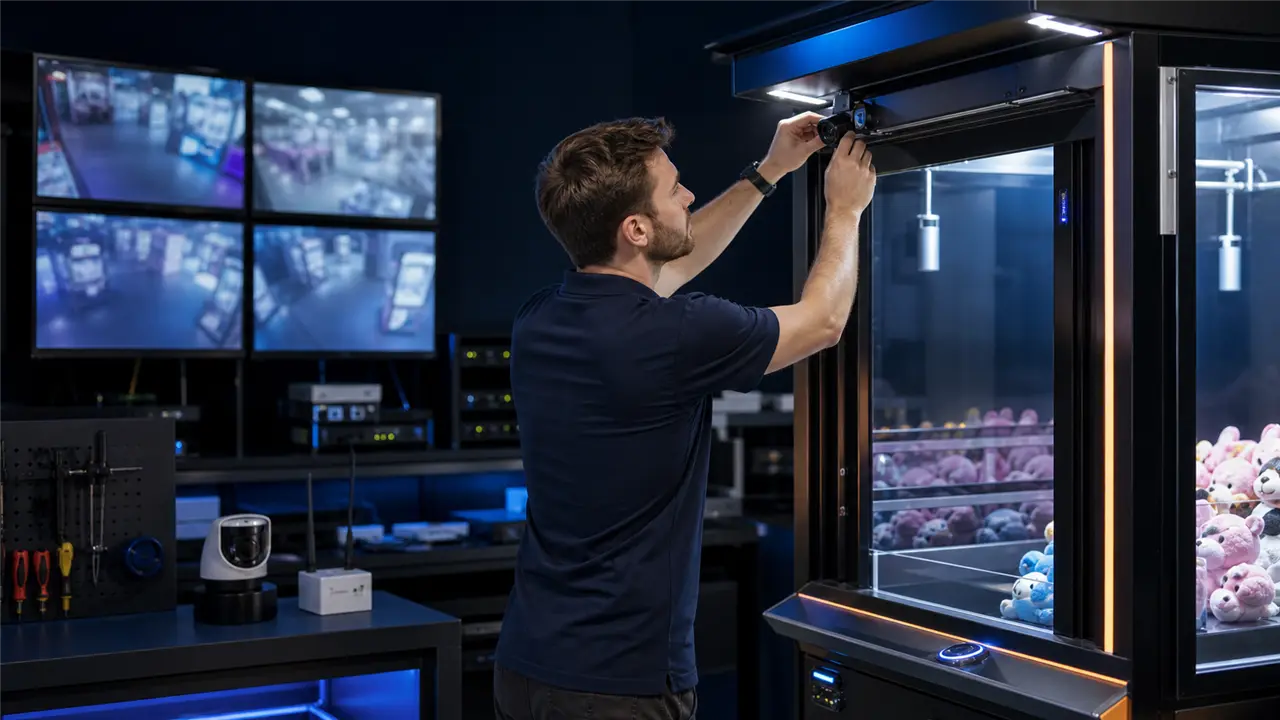
To guarantee flawless operation in a 24/7 commercial environment, the brain of the IoT controller board must be robust enough to handle simultaneous network communication, cryptographic decryption, and microsecond-accurate hardware control. Consumer-grade Wi-Fi switches typically rely on low-end single-core chips that struggle when forced to juggle network packet handling with precise hardware timing.
For our flagship teleoperation controllers, we evaluated multiple microcontroller architectures. The debate often comes down to the dual-core ESP32-S3 versus the industrial heavyweight STM32F407. The ESP32-S3 offers incredible value with integrated Wi-Fi and Bluetooth LE, making it highly attractive for cost-sensitive deployments. Its dual-core architecture allows us to pin the FreeRTOS network stack (handling MQTT messages from the payment gateway and WebRTC signaling) to Core 0, while dedicating Core 1 entirely to hardware GPIO manipulation, pulse generation, and telemetry polling. This segregation ensures that a sudden influx of network traffic never disrupts the timing of a coin pulse being sent to the JAMMA board.
However, for environments requiring extreme electromagnetic resilience and deterministic real-time performance—such as large-scale casino floors or densely packed arcade centers with hundreds of high-voltage motors running simultaneously—we often deploy the STM32F407 ARM Cortex-M4 processor. While it requires external networking silicon (such as a W5500 Ethernet controller or a cellular LTE CAT4 modem), the STM32 excels in raw hardware timer capabilities and interrupt latency.
We integrate physical watchdog timers (WDT) directly onto the PCB. Unlike software watchdogs that can freeze if the core clock stalls, our hardware watchdogs require the microcontroller to send a physical electrical pulse every 500 milliseconds. If the microcontroller hangs due to an unforeseen software exception or a severe power brownout, the independent watchdog chip physically cuts and restores power to the microcontroller, rebooting the system in milliseconds. This self-healing architecture is why our boards achieve 99.99% uptime in unattended remote venues.
Our PCB designs also utilize 4-layer FR4 boards with dedicated solid ground and power planes. This acts as a Faraday cage for the internal signal traces, drastically reducing EMI (Electromagnetic Interference) radiated by the machine’s coin hoppers and fluorescent ballasts. We mandate 2oz copper thickness for any traces handling motor driving or power delivery, ensuring thermal stability even under sustained peak loads. This is what separates a hobbyist prototyping board from a true industrial solution designed for arcade machines.
Optical Isolation Circuitry PC817 and 6N137 High-Speed Optocouplers for Complete Galvanic Separation

A fundamental rule I enforce in our hardware designs is that the logic circuitry (the microcontroller, memory, and network radios) must never share a direct electrical path with the high-voltage or electrically noisy peripheral environment. Arcade machines are notorious for electrical spikes. When a large 12V or 24V DC motor inside a coin hopper or a claw crane gantry abruptly stops, the collapsing magnetic field in the motor coils generates a massive reverse voltage spike, known as back-EMF. If your IoT board is directly wired to the machine’s ground and signal lines without protection, these transients will travel straight back into the microcontroller, causing immediate logic resets or permanent silicon damage.
To achieve complete galvanic separation, we utilize optical isolation circuitry across all input and output channels on our boards. For standard speed signals, such as coin insertion pulses, payout triggers, and switch states, we deploy arrays of PC817 optocouplers. An optocoupler consists of an internal infrared LED and a phototransistor separated by a physical gap. When the microcontroller needs to send a pulse to the arcade machine, it simply turns on the internal LED. The phototransistor on the machine’s side of the circuit detects the light and closes the circuit. Because light is the only medium bridging the gap, there is absolute electrical isolation—often rated to withstand up to 5,000 volts of transient isolation.
For high-speed data buses—such as serial communication protocols used by advanced bill acceptors, ticket dispensers, or proprietary card readers—the switching speed of standard PC817 optocouplers is too slow, leading to signal distortion and baud rate errors. In these critical pathways, we integrate 6N137 high-speed optocouplers. These utilize a logic gate output paired with a photo-detector, capable of handling data rates up to 10 MBd. This guarantees that complex serial handshakes between the IoT board and the machine peripherals remain mathematically pristine while maintaining impenetrable galvanic isolation.
> Download Our Technical Resources > We believe in total engineering transparency with our B2B partners. You can download our complete hardware schematic block diagrams, GPIO pinout maps, and REST/MQTT API documentation directly from our enterprise portal. Integrate our hardware into your existing custom dashboard seamlessly. Contact our sales engineering team to receive your encrypted download link today.
By isolating the grounds, we also eliminate ground loops—a common issue where small voltage differences between the IoT board’s power supply and the arcade machine’s power supply create unpredictable logic states. We power the isolated side of the optocouplers directly from the arcade machine’s 5V or 12V rails, while the microcontroller side runs on a rigorously filtered, dedicated buck converter on the IoT board. This dual-power architecture ensures that even if an EMP device (such as a sparker used by cheaters) is applied to the machine’s coin slot, the destructive surge cannot cross the optical barrier to compromise the IoT controller or the cloud connection.
Precision Pulse Generation Sub-Millisecond Hardware Timers for Bill Acceptor and Coin Mech Emulation
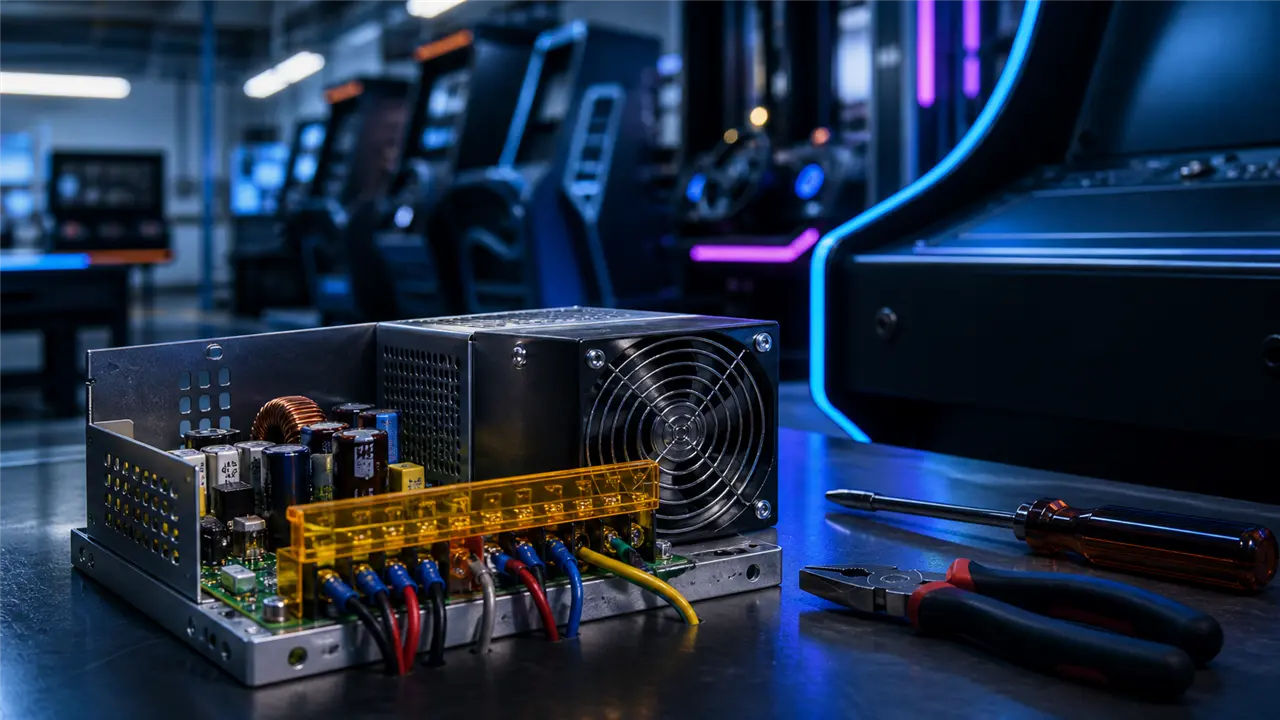
When replacing a physical bill acceptor or mechanical coin mechanism with an IoT payment gateway, the IoT board must emulate the physical hardware so perfectly that the game board cannot tell the difference. This requires precision pulse signal conversion.
Most arcade game boards adhere to strict timing tolerances for credit insertion. A standard coin pulse might require a low state (pulling the coin pin to ground) for precisely 50 milliseconds, followed by a high state (resting at 5V or 12V) for 50 milliseconds before the next pulse can be recognized. If the pulse is too short (e.g., 20ms), the game board’s debounce filter will reject it as electrical noise. If the pulse is too long (e.g., 150ms), the game board might interpret it as a coin jam or a stuck microswitch, throwing an error code and locking the machine out of service.
In poorly designed systems, programmers often use software delays to generate these pulses. They write a loop that pulls the pin low, calls a sleep(50) function, pulls the pin high, and calls sleep(50). In a multitasking operating system or an RTOS handling heavy Wi-Fi traffic, a sleep(50) command is merely a suggestion. The CPU scheduler might delay returning to that thread for an extra 30 milliseconds because it was busy decrypting a TLS packet. The result is a sloppy, jittery pulse train that the arcade board randomly rejects, leading to players being charged via the app but receiving no credits on the machine.
Our firmware completely bypasses software delays for pulse generation. We utilize the sub-millisecond hardware timers built into the silicon of the STM32 or ESP32-S3 chips. When an API command is received to add 10 credits, the networking thread passes the integer 10 to the hardware timer peripheral via a direct memory access (DMA) buffer or a strict interrupt queue. The timer hardware autonomously toggles the GPIO pin at exactly 50ms intervals, independent of the CPU core’s workload. Even if we flood the Wi-Fi chip with gigabytes of ping requests, the hardware timer continues to output a mathematically perfect, jitter-free square wave.
This hardware-level pulse conversion ensures 100% acceptance rates by the game board. We also include dip switches and digital API commands to dynamically adjust the pulse width (e.g., 30ms, 50ms, 100ms) to ensure compatibility across all generations of arcade hardware, from vintage 1990s NEO-GEO boards to modern PC-based fishing game cabinets. We have engineered the ultimate remote payment gateway pulse conversion system.
Telemetry and Bi-Directional Feedback Optical Ticket Sensor Verification and Hopper Out-of-Stock Telemetry
Teleoperation is not merely about sending commands to a machine; it is equally about reading the machine’s physical state and relaying that telemetry back to the operator and the player in real-time. A one-way control system is flying blind. If a player wins a jackpot and the system sends a command to dispense 500 tickets, how do you know the tickets were actually dispensed? What if the ticket roll is empty, or the ticket cutter is jammed?
We integrate comprehensive bi-directional feedback loops into our IoT boards to provide total situational awareness for remote operators. For ticket dispensers, we intercept the optical notch sensor signal. Every time a ticket is dispensed, a physical notch passes through an optical beam, generating a pulse. Our IoT board counts these return pulses using high-speed hardware interrupts. If the app commands 500 tickets, but the IoT board only counts 120 return pulses before a 3-second timeout occurs, our board instantly recognizes a mechanical failure. It halts the command, logs the exact number of dispensed tickets to the cloud database for accurate auditing, and triggers a push notification to the venue technician’s phone indicating a ticket jam on Machine #42.
Similarly, we interface directly with the low-level sensors of coin hoppers and prize vend motors. Coin hoppers utilize conductive plates or optical sensors to detect low-level states. We map these sensor outputs to our optically isolated GPIO inputs. When a hopper runs out of coins, our board detects the state change within milliseconds. It updates the machine’s status on the cloud server from “Online” to “Out of Stock,” automatically preventing further players from joining that specific machine via the app and avoiding catastrophic user experience failures and refund requests.
This level of telemetry is what transforms a simple remote-controlled toy into a professional-grade, highly profitable enterprise deployment. By integrating our controller boards with our larger remote live arcade teleoperation and industrial IoT solutions, operators gain a god-level view of their entire hardware fleet. We have also extensively documented our integration processes across various subsystems. For insights on managing the video pipeline, review our guide on webrtc-streaming-ip-camera-integration-remote-arcade-cabinets. If you need to understand the electrical nuances of connecting our boards to older game logic, our documentation on arcade-pcb-manufacturer-jamma-harness-standards provides invaluable wiring schematics. Furthermore, for those looking to expand beyond simple coin and ticket control to full environmental control, our deep dive into industrial-iot-controller-boards-gpio-relay-arcade-integration outlines how to command lighting and external peripherals.
FAQ Section
How does your IoT board prevent players from being charged for credits that the arcade machine fails to register? Through our hardware-timer-driven pulse generation, we eliminate signal jitter, ensuring the game board receives a perfect square wave that matches its specific timing tolerances. We combine this with a dual-database transaction handshake. The player’s digital wallet is only temporarily debited when the command is sent. Our IoT board monitors the machine’s coin meter pulse feedback. Only when the board verifies that the physical machine has registered the pulse does it send a cryptographic confirmation back to the server to finalize the transaction. If the machine rejects it, the server automatically reverses the temporary debit.
Can the controller board interface with legacy JAMMA machines that operate on 12V logic instead of modern 5V/3.3V? Absolutely. Because our entire input/output architecture utilizes PC817 and 6N137 optocouplers, the logic voltage of the arcade machine is entirely decoupled from our microcontroller’s 3.3V logic. You simply supply the machine’s 12V reference voltage to the common pin of the optocoupler array, and the board seamlessly sinks or sources 12V pulses without risking any overvoltage damage to the IoT core.
What happens if the Wi-Fi network in the arcade venue goes down temporarily? Our firmware operates on an asynchronous event-driven architecture. If the WebSocket or MQTT connection to the cloud drops, the IoT board enters a secure hold state. Any active physical operations (like a claw dropping or a motor spinning) are safely halted by the onboard watchdog rules to prevent mechanical damage. The board locally caches any pending telemetry data (such as coins won in the last few seconds) in its non-volatile flash memory. The moment the network connection is re-established, the board synchronizes the cached offline data with the cloud server, ensuring zero loss of accounting data.
Do you support custom firmware modifications for proprietary payout protocols? Yes. Since we design the PCB schematics and write the bare-metal C++ firmware in-house in Panyu, we offer full white-label customization. If your game board uses a proprietary RS232, RS485, or ccTalk encrypted protocol for bill validators or payout hoppers, our engineering team can integrate your specific baud rates and cryptographic handshakes directly into our firmware, providing you with a unified cloud API.
How do we ensure the boards are not damaged during overseas shipping or installation by untrained staff? Every board manufactured in our facility undergoes a strict FAT (Factory Acceptance Testing) protocol. They are subjected to 48 hours of continuous thermal cycling and vibration testing while under electrical load. Furthermore, all external connection terminals are heavily protected with TVS (Transient Voltage Suppressor) diodes and self-resetting PTC fuses. If an untrained technician wires the 24V power supply backward, the PTC fuse immediately trips to protect the board, and resets itself once the wiring is corrected.
> **
Commercial Risk-Reversal Guarantees for Direct Factory Procurement
To eliminate overseas purchasing hesitation and guarantee zero capital risk, our Panyu factory backs every commercial order with four ironclad commitments: 1. Low-Risk Sample Prototyping: We support 1-unit custom sample trial orders before committing to 20GP/40HQ container runs, allowing you to test physical chassis build quality, coin mech reliability, and game RTP firsthand. 2. Third-Party FAT Audits Welcome: We welcome third-party inspection teams from SGS, Intertek, or TÜV to conduct comprehensive onsite Factory Acceptance Testing on our assembly floor before container loading. 3. 100% Clean IP and Source Code Ownership: All custom software development contracts include full uncompiled Unity/C++ source code buyout with zero backdoors, perpetual commercial licenses, and clean IP indemnification. 4. 12-Hour Remote Engineering SLA: Direct WhatsApp and WeChat priority technical support groups linked directly to Engineer Wang’s hardware lab for live video debugging, schematic reviews, and replacement component dispatch.
Partner with the Manufacturing Experts** > Are you ready to scale your remote arcade operations with hardware engineered for 24/7 profitability? Stop losing money to consumer-grade relays and unreliable networking. Our team in Panyu is ready to custom-tailor an industrial IoT solution for your specific venue requirements. > > Direct Engineering Contact > – WhatsApp / WeChat: +86 17620842078 > – Telegram: https://t.me/JLwyc > – Email: miba515527@gmail.com > > Contact us today to discuss bulk pricing, request engineering samples, or schedule a FAT factory visit booking to see our manufacturing and QA lines in person. We are Guangzhou Miba Animation Technology Co., Ltd. — your ultimate arcade hardware partner.