- The Engineering Foundation of Standardized Arcade Wiring
- Comprehensive 56 Pin JAMMA Edge Connector Pinout Specification
- Power Distribution and Voltage Regulation Best Practices
- Wire Gauge and Terminal Crimp Standards for Commercial Durability
- Noise Suppression and Signal Integrity in Video and Audio Paths
- Mechanical Switch Debouncing and Input Architecture
- Advanced Grounding Architectures to Eliminate Ground Loops
- Troubleshooting Preventive Maintenance and Multimeter Diagnostics
- Custom Wiring Harness Manufacturing for B2B Operations
- Frequently Asked Questions
The commercial amusement industry relies on continuous operation and maximum uptime to secure a steady return on investment. At the heart of this reliability lies the electrical backbone of the hardware. The jamma arcade pcb wiring harness industrial standard represents the foundational architecture that connects high-performance game logic boards with mechanical inputs, displays, and power supplies. Engineered to withstand the relentless abuse of high-traffic commercial environments, these standardized wiring assemblies ensure that arcade cabinets can operate 24 hours a day, 7 days a week without spontaneous component failure or hazardous electrical faults.
Understanding the electrical and mechanical principles behind these wiring looms is critical for hardware architects, factory engineers, and operational managers. A poorly manufactured harness inevitably leads to voltage drops, logic errors, floating ground states, and electromagnetic interference that disrupts video synchronization. Conversely, a meticulously crafted harness, utilizing appropriate wire gauges, mechanically secure crimps, and robust noise suppression techniques, guarantees decades of flawless operation. This technical documentation will explore the precise engineering requirements necessary to fabricate, install, and maintain industrial grade 56 pin JAMMA wiring assemblies. For a comprehensive architectural overview and turnkey procurement frameworks, review our master guide on arcade machine metal fabrication guide. For factory-direct procurement and comprehensive engineering specs, consult our master guide on arcade game machine manufacturing and custom cabinet sourcing.
If you are outfitting a new commercial entertainment center, manufacturing custom hardware, or simply requiring robust components for thousands of machines, partnering with a proven industrial manufacturer is essential. For immediate technical consultations and wholesale manufacturing quotes on premium arcade wiring systems and cabinets, reach out to Engineer Wang via WhatsApp at +86 17620842078, connect on Telegram at https://t.me/JLwyc, or Email miba515527@gmail.com To explore detailed technical specifications and deployment considerations, see our operational guide on How Operators Procure Wholesale Casino Redemption. To explore detailed technical specifications and deployment considerations, see our operational guide on How Casino Machine Manufacturers Engineer OEM.
The Engineering Foundation of Standardized Arcade Wiring
Before the widespread adoption of the Japan Amusement Machine and Marketing Association (JAMMA) standard in the late 1980s, commercial game operators faced a logistical nightmare. Every manufacturer utilized proprietary edge connectors, disparate pin configurations, and unique power delivery requirements. Swapping a game board required completely rewiring the cabinet, costing significant labor hours and increasing the risk of catastrophic electrical shorts. The introduction of the 56 pin edge connector revolutionized the industry by creating a universal electrical interface.
The JAMMA standard specifies a 56 pin card edge connector, configured as a 2×28 dual row matrix with a 3.96mm (0.156 inch) contact pitch. This specific pitch allows for robust copper pads on the printed circuit board capable of handling substantial current delivery, particularly on the primary +5V DC power rails. The physical edge connector is typically manufactured with phosphor bronze contacts plated with hard gold over a nickel underplate, ensuring low contact resistance and high durability across hundreds of insertion and extraction cycles.
Modern commercial manufacturing environments mandate strict adherence to these electrical parameters. The harness must accommodate multiple distinct subsystems including high current power distribution, sensitive analog RGB video signals, unamplified speaker outputs, and digital logic inputs from microswitches. Integrating these disparate signal types into a single bundled loom requires careful consideration of electromagnetic interference, capacitive coupling between adjacent wires, and adequate return paths to common ground.
Comprehensive 56 Pin JAMMA Edge Connector Pinout Specification
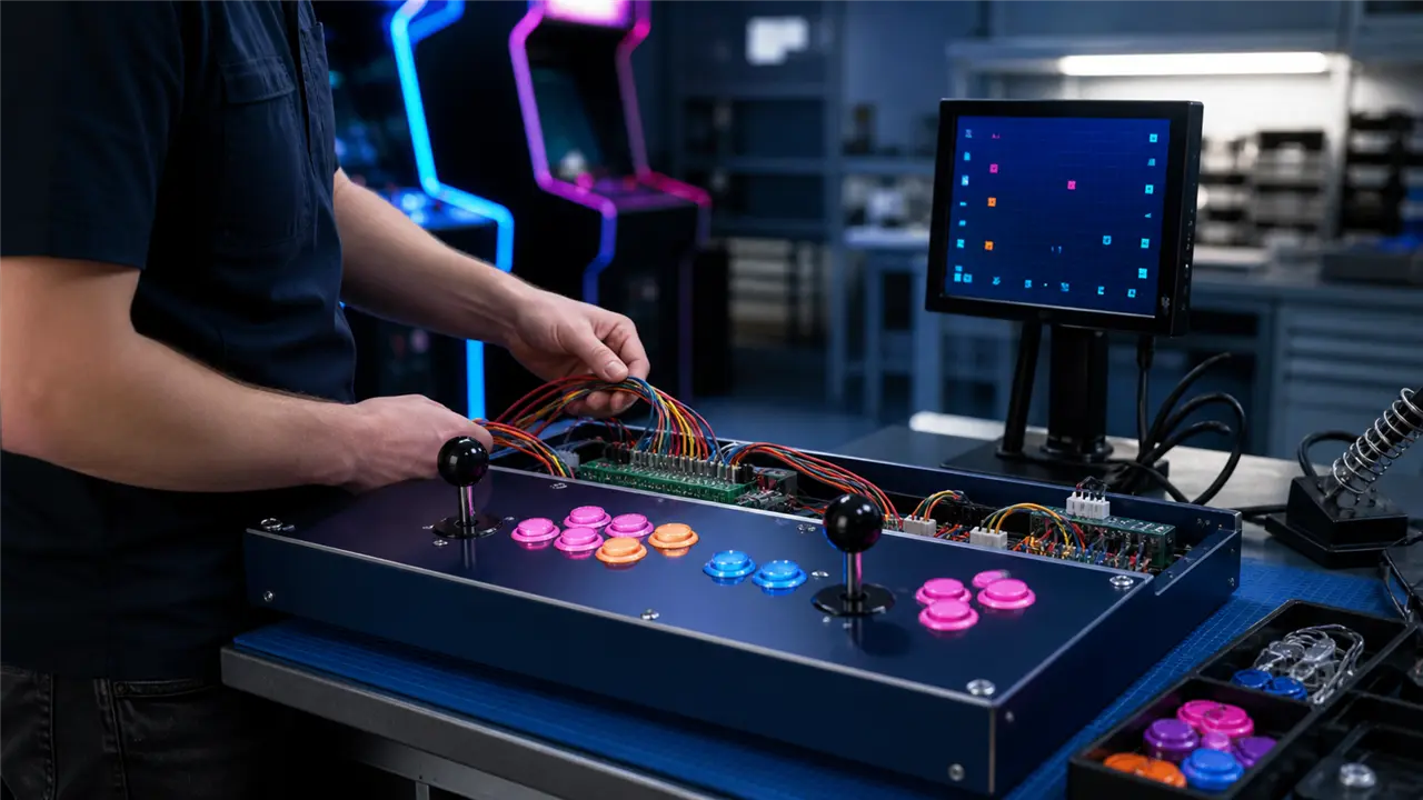
The absolute core of the standard is the pinout mapping. The edge connector features two sides designated as the Solder Side (labeled with uppercase and lowercase letters A through Z, then a through f, skipping I, O, Q to avoid visual confusion) and the Parts Side (labeled with numerals 1 through 28). The Parts Side refers to the top surface of the PCB where the integrated circuits and capacitors are mounted, while the Solder Side is the bottom surface.
Below is the definitive industrial engineering pinout table for standard PCB modules.
Solder Side (Bottom) vs Parts Side (Top)
| Pin | Solder Side Function | Parts Side Function | Pin |
|---|---|---|---|
| A | Ground (GND) | Ground (GND) | 1 |
| B | Ground (GND) | Ground (GND) | 2 |
| C | +5V DC Power | +5V DC Power | 3 |
| D | +5V DC Power | +5V DC Power | 4 |
| E | -5V DC Power | -5V DC Power | 5 |
| F | +12V DC Power | +12V DC Power | 6 |
| H | Key / Index Slot | Key / Index Slot | 7 |
| J | Coin Counter 2 | Coin Counter 1 | 8 |
| K | Coin Lockout 2 | Coin Lockout 1 | 9 |
| L | Speaker (-) | Speaker (+) | 10 |
| M | Audio Ground (Optional) | Audio (+) | 11 |
| N | Video Green (G) | Video Red (R) | 12 |
| P | Video Sync (CSYNC) | Video Blue (B) | 13 |
| R | Service Switch | Video Ground (GND) | 14 |
| S | Tilt Switch (Slam) | Test Switch | 15 |
| T | Coin Switch 2 | Coin Switch 1 | 16 |
| U | Player 2 Start | Player 1 Start | 17 |
| V | Player 2 Up | Player 1 Up | 18 |
| W | Player 2 Down | Player 1 Down | 19 |
| X | Player 2 Left | Player 1 Left | 20 |
| Y | Player 2 Right | Player 1 Right | 21 |
| Z | Player 2 Button 1 | Player 1 Button 1 | 22 |
| a | Player 2 Button 2 | Player 1 Button 2 | 23 |
| b | Player 2 Button 3 | Player 1 Button 3 | 24 |
| c | Not Connected / Button 4 | Not Connected / Button 4 | 25 |
| d | Not Connected / Button 5 | Not Connected / Button 5 | 26 |
| e | Ground (GND) | Ground (GND) | 27 |
| f | Ground (GND) | Ground (GND) | 28 |
Engineers must pay careful attention to pins 7 and H. This position contains an physical polarization key (usually a small piece of plastic inserted into the edge connector). This index slot prevents operators from inserting the PCB backwards. Reversing the connector would inject +12V into ground rails and ground into +5V logic inputs, instantly destroying the application specific integrated circuits on the logic board.
Power Distribution and Voltage Regulation Best Practices
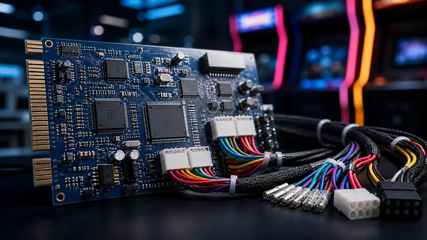
Delivering clean, stable power to the PCB is the most critical function of the harness. The logic ICs (such as CPU, RAM, and ROM chips) depend entirely on the +5V DC rail. Commercial switching power supplies (SMPS) utilized in cabinets typically provide an adjustable +5V output, a fixed +12V output for audio amplification and coin mechanisms, and sometimes a -5V output required by legacy operational amplifiers in older audio circuits.
The physics of direct current transmission dictates that resistance in the wiring will cause a voltage drop. This relationship is defined by Ohm’s Law and the resistivity of copper. The formula for calculating voltage drop along a wire is:
$V_{drop} = \frac{2 \times L \times R \times I}{1000}$
Where $L$ is the length in feet, $R$ is the resistance of the wire per 1000 feet, and $I$ is the current load in Amperes. A typical multi game system board can draw anywhere from 3 Amps to 7 Amps on the +5V rail. If thin, substandard wiring is used, a 5.1V output at the power supply may degrade to 4.7V by the time it reaches the PCB. When TTL (Transistor-Transistor Logic) chips receive voltage below 4.75V, they enter an undefined state, resulting in system resets, watchdog timer triggers, or graphical artifacting known as “glitching.”
To eliminate these failures, industrial standards mandate connecting all four available +5V pins (C, D, 3, 4) and all four main ground pins (A, B, 1, 2) in parallel. Distributing the current across multiple contacts prevents any single edge connector pad from overheating, melting the plastic housing, and causing a critical short circuit.
Wire Gauge and Terminal Crimp Standards for Commercial Durability
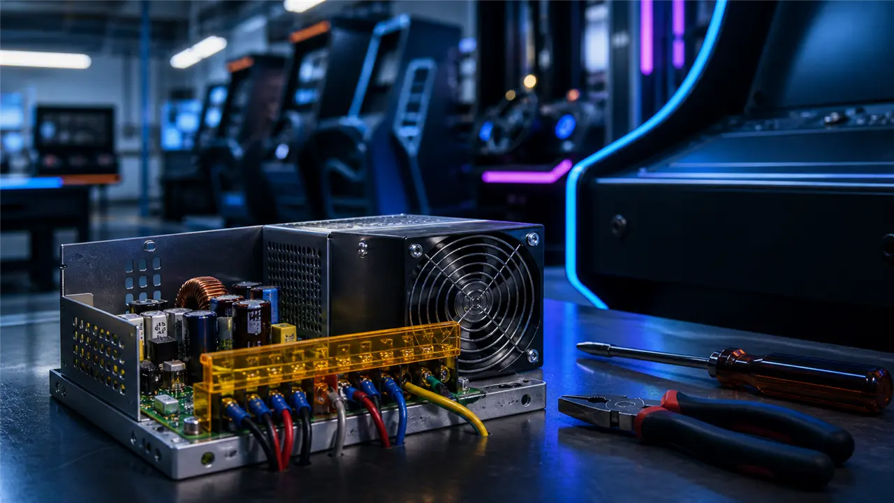
Selecting the correct American Wire Gauge (AWG) specification is paramount for commercial manufacturing. High quality harnesses utilize cross linked polyethylene (XLPE) or high temperature polyvinyl chloride (PVC) insulated stranded copper wire. Stranded wire provides necessary flexibility to route through the cabinet geometry without succumbing to metal fatigue from repeated cabinet door opening and closing.
For the power delivery lines (+5V, +12V, -5V, and Power Ground), the industrial standard requires 18 AWG wiring. 18 AWG has a sufficiently large cross sectional area to handle up to 10 Amps of continuous current with minimal thermal generation. For signal lines, including video, audio, and switch inputs, 22 AWG wire is the standard choice. Logic signals operate at practically zero current (typically pulling a 5V logic high to ground), so thicker wire is unnecessary and merely increases the stiffness and cost of the loom.
The mechanical interface between the wire and the control components requires precision crimping. Arcade joysticks and microswitches typically feature either 0.187 inch (4.8mm) or 0.250 inch (6.3mm) male spade tabs. The wiring harness must be equipped with matching female quick disconnect terminals.
Engineers mandate the use of ratcheting crimp tools to cold weld the terminal barrel to the stranded wire. Proper crimping displaces the copper strands, eliminating microscopic air gaps and preventing oxidation which could lead to high resistance connections over years of operation. Furthermore, all female disconnects must be insulated with silicone or heavy duty PVC strain relief boots. These boots protect adjacent terminals from arcing and prevent short circuits if a wire is accidentally detached during routine maintenance.
To upgrade your facility with components built to these exacting industrial specifications, secure your supply chain with a premier manufacturer. Contact Engineer Wang via WhatsApp at +86 17620842078, Telegram at https://t.me/JLwyc, or Email miba515527@gmail.com for bulk pricing on specialized arcade components.
Noise Suppression and Signal Integrity in Video and Audio Paths
Commercial cabinets are extremely noisy electromagnetic environments. The switching power supply generates high frequency ripple, fluorescent marquees emit significant EMI, and coin door solenoids produce massive inductive spikes when deactivated. Protecting the sensitive analog RGB video signals and unamplified audio lines from this interference requires meticulous engineering.
The video output from a PCB consists of separate Red, Green, Blue, and Composite Sync signals operating at approximately 1V to 5V peak to peak. If these lines run parallel and unshielded alongside a pulsing +12V coin lockout wire, inductive coupling will induce noise into the video signal, manifesting as rolling static bars, color bleeding, or loss of horizontal synchronization on the CRT or LCD monitor.
To maintain signal integrity, industrial harnesses often twist the RGB lines together with a dedicated video ground line. This twisted pair configuration forces induced electromagnetic fields to cancel each other out. Additionally, high end manufacturing processes include the installation of ferrite bead chokes around the video bundle near the edge connector. These ferrite cores act as passive low pass filters, absorbing high frequency EMI and converting it to negligible amounts of heat, thereby purifying the analog transmission.
Audio lines (Pins 10 and L) require similar treatment. In the JAMMA standard, the audio output is typically directly driven by an onboard amplifier to a 4 Ohm or 8 Ohm speaker. Because this is a high level amplified signal rather than a line level signal, it is slightly more resistant to interference. However, routing the speaker wires away from AC mains input lines and utilizing shielded cabling is strongly recommended to prevent an audible 50Hz or 60Hz mains hum from degrading the user experience.
Mechanical Switch Debouncing and Input Architecture
The interaction between the player and the machine occurs via mechanical microswitches located in the joysticks and pushbuttons. The JAMMA standard utilizes active low logic. This means that the input pins on the PCB are internally pulled up to +5V using resistor networks. When a player presses a button, the microswitch closes the circuit, connecting the input pin directly to the common ground rail (Pins 27, 28, e, f), dropping the voltage at the logic gate to 0V.
A significant challenge in mechanical switch engineering is contact bounce. When the metal contacts inside the microswitch snap together, they physically rebound at a microscopic level multiple times before settling into a solid connection. Without proper engineering, the CPU would register this bounce as multiple rapid button presses, destroying gameplay precision in fighting games or shooting titles.
While most modern PCBs handle debouncing via software algorithms or hardware Schmitt triggers, the wiring harness plays a role in minimizing this effect. Utilizing low resistance 22 AWG wire and maintaining clean, tightly crimped connections ensures that the transition from 5V to 0V is as sharp as possible, allowing the board’s logic to effectively filter out the mechanical noise. A common ground daisy chain wire is typically routed from switch to switch on the control panel, finally terminating at the main ground pins on the edge connector.
Advanced Grounding Architectures to Eliminate Ground Loops
A critical design flaw found in amateur or poorly manufactured cabinets is the existence of ground loops. A ground loop occurs when there are multiple paths to electrical ground, and these paths possess differing resistances. This discrepancy creates a small voltage potential between the two ground points, allowing stray currents to flow through signal grounds rather than the main power ground.
In a commercial arcade cabinet, a ground loop often causes severe video distortion, audio buzzing, and erratic input behavior. Industrial engineers solve this by implementing a strict star grounding topology. In this configuration, all ground connections—the switching power supply ground, the monitor chassis ground, the coin mechanism ground, and the control panel common ground—must physically meet at a single, central ground bus bar or directly at the power supply’s ground terminal.
The JAMMA harness must reflect this architecture. The Video Ground (Pin 14) must be kept strictly separate from the main power grounds until they meet at the central star point. Tying the video ground directly to the logic ground on the harness itself can force high current return paths to flow through the monitor chassis, leading to catastrophic interference.
Troubleshooting Preventive Maintenance and Multimeter Diagnostics
Maintaining a fleet of arcade cabinets requires rigorous preventive maintenance protocols. The primary diagnostic tool for a hardware engineer is a high quality True RMS digital multimeter. The most critical maintenance procedure is the under load voltage calibration.
When installing a new logic board, the technician must measure the +5V DC rail directly at the JAMMA edge connector (across pins 1 and 3), not at the power supply terminals. The measurement must be taken while the board is running its most graphically intense sequence, ensuring maximum current draw. The power supply’s potentiometer must then be carefully adjusted until the multimeter reads exactly +5.05V to +5.10V at the edge connector. This slight overvoltage compensates for any instantaneous transient current demands without exceeding the 5.25V absolute maximum rating of standard TTL components.
Technicians must also visually inspect the edge connector regularly for signs of oxidation or thermal degradation. If the gold plating on the PCB edge wears thin, exposing the underlying copper, oxidation will rapidly increase contact resistance. This localized resistance generates heat, which can ultimately char the plastic housing of the harness connector. Applying a high quality electronic contact cleaner and a microscopic layer of conductive dielectric grease can drastically extend the lifespan of the connection matrix.
Furthermore, checking the continuity of the daisy chained ground wire on the control panel is essential. A broken ground wire will instantly disable all buttons and joysticks downstream from the break, leading to immediate player frustration and lost revenue.
Custom Wiring Harness Manufacturing for B2B Operations
For large scale arcade manufacturers and casino platform operators, utilizing off the shelf wiring solutions is rarely sufficient. Modern setups often require expansions beyond the original 56 pins to accommodate proprietary card readers, advanced ticket dispensers, specialized lighting controllers, and multi screen synchronization protocols.
Custom harness manufacturing involves detailed schematic design, automated wire cutting and stripping machines to ensure millimeter perfect lengths, and pneumatic crimping presses for zero defect terminal attachments. Quality assurance protocols must include automated continuity testing across all pins, high voltage hi-pot testing to guarantee insulation integrity, and strict adherence to UL and CE safety certifications.
When your enterprise requires specialized electrical engineering and high volume production of flawless wiring assemblies, you need a partner who understands the rigorous demands of the global amusement industry. For comprehensive technical support, custom design consultations, and competitive manufacturing quotes, contact Engineer Wang today via WhatsApp at +86 17620842078, message on Telegram at https://t.me/JLwyc, or Email miba515527@gmail.com Build your hardware foundation on uncompromising industrial standards.
Frequently Asked Questions
What is the difference between a JAMMA harness and a JVS harness? The original 56 pin standard relies on direct parallel connections where every button and signal has a dedicated wire operating on TTL logic levels. JVS (JAMMA Video Standard) represents a modernization that utilizes a decentralized architecture. In JVS systems, power is delivered via dedicated heavy duty connectors, video is transmitted over standard VGA or DVI cables, and all input and output signals are serialized over a digital USB cable connected to a separate I/O board. JVS dramatically simplifies wiring complexity but requires conversion boards to operate legacy hardware.
Why does the +5V rail require four separate pins on the edge connector? Arcade PCB components, particularly CPUs and high speed RAM, draw substantial current. A single edge connector pin and pad can safely handle approximately 2.5 to 3 Amps of current before thermal issues arise. Because complex boards can draw upwards of 7 Amps on the +5V rail, distributing this load across four pins (C, D, 3, 4) ensures the current per pin remains safely below the maximum threshold, preventing the connector from overheating or melting.
What wire gauge should be used for the power and signal lines? Industrial standards strictly dictate using 18 AWG stranded copper wire for all primary power delivery lines, including +5V, +12V, -5V, and the main grounds. This gauge handles the necessary current with minimal voltage drop. For signal lines such as joystick inputs, action buttons, and coin microswitches, 22 AWG wire is standard. Signal lines carry virtually no current, making 22 AWG structurally sound while maintaining flexibility for routing through complex cabinet geometries.
How do you eliminate audio buzzing in a commercial cabinet? Audio buzzing, often a 50Hz or 60Hz hum, is typically caused by electromagnetic interference or ground loops. To eliminate this, ensure that the audio lines (Pins 10 and L) are twisted together and kept physically separated from the AC mains wiring and the switching power supply. Additionally, verify that your cabinet follows a strict star grounding topology, where the audio ground, video ground, and power grounds do not loop back on themselves but meet at one single, central grounding point.